Precision-digital PD6000 User Manual
Browse online or download User Manual for Control panel Precision-digital PD6000. Precision Digital PD6000 User Manual
- Page / 96
- Table of contents
- TROUBLESHOOTING
- BOOKMARKS
Rated. / 5. Based on customer reviews
PRECISION DIGITAL CORPORATION
89 October Hill Road • Holliston MA 01746 USA
Tel (800) 343-1001 • Fax (508) 655-8990
www.predig.com
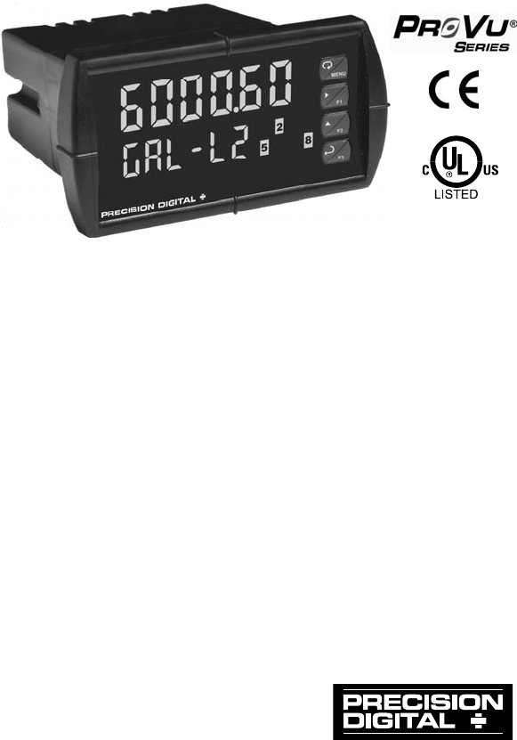
PD6000 Analog Input Process Meter
Instruction Manual
0-20 mA, 4-20 mA, 0-5 V, 1-5 V, and ±10 V Inputs
NEMA 4X, IP65 Front
Universal 85-265 VAC or 12/24 VDC Input Power
Large Dual-Line 6-Digit Display, 0.60" & 0.46"
Dual-Scale for Level Applications – Single Input
Isolated 24 VDC @ 200 mA Transmitter Power Supply
Math Functions for Flow & Round Horizontal Tanks
Programmable Display & Function Keys
32-Point, Square Root, or Exponential Linearization
Multi-Pump Alternation Control
2 or 4 Relays + Isolated 4-20 mA Output Options
External 4-Relay & Digital I/O Expansion Modules
RS-232, RS-422/485 Serial Communication Options
Modbus
®
RTU Communication Protocol Standard
- Instruction Manual 1
- Disclaimer 2
- Limited Warranty 2
- Registered Trademarks 2
- Table of Contents 3
- Table of Figures 6
- INTRODUCTION 6
- ORDERING INFORMATION 7
- SPECIFICATIONS 8
- Process Input 9
- RTU Serial Communications 11
- COMPLIANCE INFORMATION 13
- SAFETY INFORMATION 14
- INSTALLATION 15
- MAIN BOARD 16
- Connections 17
- Power Connections 18
- Connectors Labeling 18
- Warning! 18
- Signal Connections 19
- Relay Connections 20
- Switching Inductive Loads 21
- 4-20 mA Output Connections 22
- RLY5 RLY6 RLY7 RLY8 23
- NO C NO C NO C NO C 23
- DI 1-4 DO 1-4 24
- 5 VDC GND 24
- SETUP AND PROGRAMMING 25
- PV1 & PV2 scales 30
- Increment Digit 31
- Display Setup Menu 35
- prog sCale 37
- MeterView 38
- Pro Software 38
- Scaling the Meter (SCALE) 39
- SCALE), page 39 42
- Setting the Relay Action 45
- Setting Fail-Safe Operation 46
- Programming Time Delay 46
- Manual (latching) 47
- Automatic (non-latching) 47
- Relay Sampling Operation 52
- On (Go to alarm condition) 53
- Time Delay Operation 54
- Relay Operation Details 55
- Front Panel LEDs 56
- Non-Latching Relay (Auto) 57
- Non-Latching Relay (A-man) 57
- Latching Relay (LatcH) 57
- 12345678910 58
- Pump Alternation Operation 59
- Setting Numeric 63
- Password 65
- 20.000 66
- user ICAL Copy diaG 66
- Advanced 67
- Features 67
- Noise Filter (filter) 69
- Noise Filter Bypass (bypass) 69
- Select Menu (SElect) 71
- Square) 72
- Prog E) 72
- Linear) 72
- Low-Flow Cutoff (CutofF) 74
- ICAL) and press Enter 76
- C CAL) or voltage 76
- C lo). Apply the 77
- C Hi). Apply the 77
- Meter Copy Function (Copy) 79
- PDA1200 Meter Copy Cable 79
- CPY rC while being pro 80
- METER OPERATION 81
- Maximum/Minimum Readings 82
- TROUBLESHOOTING 83
- reset diaG 84
- Paramete 85
- Troubleshooting Tips 88
- MOUNTING DIMENSIONS 95
- LIM6000_E.doc 96
- SFT039 Ver 2.000 & up 96
Summary of Contents
Page 1 - Instruction Manual
PRECISION DIGITAL CORPORATION 89 October Hill Road • Holliston MA 01746 USA Tel (800) 343-1001 • Fax (508) 655-8990 www.predig.com PD6000 Analog Inp
Page 2 - Registered Trademarks
Model PD6000 Analog Input Process Meter Instruction Manual 10 DECIMAL POINT Up to five decimal places or none: d.ddddd, d.dddd, d.ddd, d.dd
Page 3 - Table of Contents
Model PD6000 Analog Input Process Meter Instruction Manual 11 AUTO INITIALIZATION When power is applied to the meter, relays will reflect th
Page 4
Model PD6000 Analog Input Process Meter Instruction Manual 12 PDA1044 Digital Input & Output Expansion Module CHANNELS 4 digital inputs
Page 5
Model PD6000 Analog Input Process Meter Instruction Manual 13 COMPLIANCE INFORMATION Safety UL & c-UL LISTED USA & Canada UL 508 Ind
Page 6 - INTRODUCTION
Model PD6000 Analog Input Process Meter Instruction Manual 14 Note: Testing was conducted on PD6000 meters installed through the covers of g
Page 7 - ORDERING INFORMATION
Model PD6000 Analog Input Process Meter Instruction Manual 15 INSTALLATION There is no need to remove the meter from its case to complete the
Page 8 - SPECIFICATIONS
Model PD6000 Analog Input Process Meter Instruction Manual 16 PanelGasketMountingBracketMountingScrewRemovableConnectors Figure 2. Panel Moun
Page 9 - Process Input
Model PD6000 Analog Input Process Meter Instruction Manual 17 Transmitter Supply Voltage Selection (P+, P-) All meters, including models equi
Page 10
Model PD6000 Analog Input Process Meter Instruction Manual 18 Connectors Labeling The connectors’ label, affixed to the meter, shows the loca
Page 11 - RTU Serial Communications
Model PD6000 Analog Input Process Meter Instruction Manual 19 Signal Connections Signal connections are made to a five-terminal connector lab
Page 12
Model PD6000 Analog Input Process Meter Instruction Manual 2 Disclaimer The information contained in this document is subject to change with
Page 13 - COMPLIANCE INFORMATION
Model PD6000 Analog Input Process Meter Instruction Manual 20 -++VoltageSignalmA+P-21354P+ V+COMINPUT SIGNALmA+P-21354P+ V+COMINPUT SIGNAL3-W
Page 14 - SAFETY INFORMATION
Model PD6000 Analog Input Process Meter Instruction Manual 21 Switching Inductive Loads The use of suppressors (snubbers) is strongly recomme
Page 15 - INSTALLATION
Model PD6000 Analog Input Process Meter Instruction Manual 22 4-20 mA Output Connections Connections for the 4-20 mA transmitter output are m
Page 16 - MAIN BOARD
Model PD6000 Analog Input Process Meter Instruction Manual 23 External Relays & Digital I/O Connections The relay and the digital I/O exp
Page 17 - Connections
Model PD6000 Analog Input Process Meter Instruction Manual 24 123456+5 I1 I2 I3 I4 O178O2 O3910O4 GDI 1-4 DO 1-45 VDC GND Figure 16. Digital
Page 18 - Warning!
Model PD6000 Analog Input Process Meter Instruction Manual 25 SETUP AND PROGRAMMING The meter is factory calibrated prior to shipment to re
Page 19 - Signal Connections
Model PD6000 Analog Input Process Meter Instruction Manual 26 Front Panel Buttons and Status LED Indicators Button Symbol Description LED
Page 20 - Relay Connections
Model PD6000 Analog Input Process Meter Instruction Manual 27 Display Functions & Messages The meter displays various functions and messa
Page 21 - Switching Inductive Loads
Model PD6000 Analog Input Process Meter Instruction Manual 28 Display Parameter Action/Setting Description d-Inty Display intensity Set disp
Page 22 - 4-20 mA Output Connections
Model PD6000 Analog Input Process Meter Instruction Manual 29 Display Parameter Action/Setting Description ignore Ignore Ignore loop break co
Page 23 - NO C NO C NO C NO C
Model PD6000 Analog Input Process Meter Instruction Manual 3 Table of Contents INTRODUCTION -------------------------------------------------
Page 24 - 5 VDC GND
Model PD6000 Analog Input Process Meter Instruction Manual 30 Main Menu The main menu consists of the most commonly used functions: Reset, Co
Page 25 - SETUP AND PROGRAMMING
Model PD6000 Analog Input Process Meter Instruction Manual 31 Setting Numeric Values The numeric values are set using the Right and Up arrow
Page 26
Model PD6000 Analog Input Process Meter Instruction Manual 32 Setting Up the Meter (setup) The Setup menu is used to select: 1. Input signal
Page 27
Model PD6000 Analog Input Process Meter Instruction Manual 33 Setting the Input Signal (input) Enter the Input menu to set up the meter to di
Page 28
Model PD6000 Analog Input Process Meter Instruction Manual 34 Setting the Display Parameter & Intensity (dsplay) The main display (Big)
Page 29
Model PD6000 Analog Input Process Meter Instruction Manual 35 Display Setup Menu Dsplay setup big dsplay Little dsplay d-Inty dsplay Int 1
Page 30 - PV1 & PV2 scales
Model PD6000 Analog Input Process Meter Instruction Manual 36 Character Set for Engineering Units Display (d unit) The small display can be p
Page 31 - Increment Digit
Model PD6000 Analog Input Process Meter Instruction Manual 37 Programming the Meter (prog) It is very important to read the following informa
Page 32
Model PD6000 Analog Input Process Meter Instruction Manual 38 Multi-Point Calibration & Scaling The meter is set up at the factory for 2-
Page 33
Model PD6000 Analog Input Process Meter Instruction Manual 39 Scaling the Meter (SCALE) The process input (4-20 mA, 10 VDC) can be scaled to
Page 34
Model PD6000 Analog Input Process Meter Instruction Manual 4 Reset Menu (reset) ------------------------------------------------------------
Page 35 - Display Setup Menu
Model PD6000 Analog Input Process Meter Instruction Manual 40 Dual-Scale for Level Application The analog input can be displayed in two diffe
Page 36
Model PD6000 Analog Input Process Meter Instruction Manual 41 Error Message (Error) An error message indicates that the calibration or scali
Page 37 - prog sCale
Model PD6000 Analog Input Process Meter Instruction Manual 42 Calibrating the Meter with External Source (Cal) To scale the meter without a s
Page 38 - Pro Software
Model PD6000 Analog Input Process Meter Instruction Manual 43 Setting the Relay Operation (relay) This menu is used to set up the operation o
Page 39 - Scaling the Meter (SCALE)
Model PD6000 Analog Input Process Meter Instruction Manual 44 relay setup rly 1 relay delay relay dly 1 delay on dly 1 Act 1 rly 1 set
Page 40
Model PD6000 Analog Input Process Meter Instruction Manual 45 Setting the Relay Action Operation of the relays is programmed in the Action me
Page 41
Model PD6000 Analog Input Process Meter Instruction Manual 46 Programming Set and Reset Points High alarm indication: program set point above
Page 42 - SCALE), page 39
Model PD6000 Analog Input Process Meter Instruction Manual 47 Relay and Alarm Operation Diagrams The following graphs illustrate the operatio
Page 43
Model PD6000 Analog Input Process Meter Instruction Manual 48 Low Alarm Operation (Set < Reset) ResetSetInputRelayLEDenergizedde-energize
Page 44
Model PD6000 Analog Input Process Meter Instruction Manual 49 High Alarm with Fail-Safe Operation (Set > Reset) RelayLEDInputAutomatic (n
Page 45 - Setting the Relay Action
Model PD6000 Analog Input Process Meter Instruction Manual 5 Acknowledging Relays ------------------------------------------------------ 58P
Page 46 - Programming Time Delay
Model PD6000 Analog Input Process Meter Instruction Manual 50 Low Alarm with Fail-Safe Operation (Set < Reset) ResetSetInputRelayLEDAutom
Page 47 - Automatic (non-latching)
Model PD6000 Analog Input Process Meter Instruction Manual 51 Pump Alternation Control Operation Pump 1Relay1 SetRelay2 ResetRelay2 SetR
Page 48
Model PD6000 Analog Input Process Meter Instruction Manual 52 Relay Sampling Operation SetResetRelayLEDInputSampleTimeSampleTimeSampleTime
Page 49
Model PD6000 Analog Input Process Meter Instruction Manual 53 Signal Loss or Loop Break Relay Operation The following graph shows the loop b
Page 50
Model PD6000 Analog Input Process Meter Instruction Manual 54 Time Delay Operation The following graphs show the operation of the time delay
Page 51
Model PD6000 Analog Input Process Meter Instruction Manual 55 Relay Operation Details Overview The relay capabilities of the meter expand its
Page 52 - Relay Sampling Operation
Model PD6000 Analog Input Process Meter Instruction Manual 56 Front Panel LEDs The LEDs on the front panel provide status indication for the
Page 53 - On (Go to alarm condition)
Model PD6000 Analog Input Process Meter Instruction Manual 57 Non-Latching Relay (Auto) Automatic reset only Condition LED RelayNormal Off Of
Page 54 - Time Delay Operation
Model PD6000 Analog Input Process Meter Instruction Manual 58 Latching Relay (Lt-Clr) Manual reset only after alarm condition has cleared Con
Page 55 - Relay Operation Details
Model PD6000 Analog Input Process Meter Instruction Manual 59 Pump Alternation Control Applications (Altern) For pump control applications wh
Page 56 - Front Panel LEDs
Model PD6000 Analog Input Process Meter Instruction Manual 6 Table of Figures Figure 1. 1/8 DIN Panel Cutout Dimensions ...
Page 57 - Latching Relay (LatcH)
Model PD6000 Analog Input Process Meter Instruction Manual 60 Application #2: Pump Alternation Using Relays 3 & 4 1. Relays 1 and 2 are
Page 58 - 12345678910
Model PD6000 Analog Input Process Meter Instruction Manual 61 3. If the backup pump is not able to keep up, and the level reaches 7000 gal
Page 59 - Pump Alternation Operation
Model PD6000 Analog Input Process Meter Instruction Manual 62 Setting Up the Interlock Relay Feature Relays 1-4 can be set up as interlock re
Page 60
Model PD6000 Analog Input Process Meter Instruction Manual 63 Scaling the 4-20 mA Analog Output (Aout) The 4-20 mA analog output can be scale
Page 61
Model PD6000 Analog Input Process Meter Instruction Manual 64 Setting Up the Password (pass) The Password menu is used for programming three
Page 62
Model PD6000 Analog Input Process Meter Instruction Manual 65 Making Changes to a Password Protected Meter If the meter is password protected
Page 63 - Setting Numeric
Model PD6000 Analog Input Process Meter Instruction Manual 66 Advanced Features Menu To simplify the setup process, functions not needed for
Page 64
Model PD6000 Analog Input Process Meter Instruction Manual 67 Advanced Features Menu & Display Messages The following table shows the fun
Page 65 - Password
Model PD6000 Analog Input Process Meter Instruction Manual 68 Display Parameter Action/Setting O-rang Overrange Program mA output for displa
Page 66 - user ICAL Copy diaG
Model PD6000 Analog Input Process Meter Instruction Manual 69 Display Parameter Action/Setting Input Input Input selection Filter Filter Fil
Page 67 - Features
Model PD6000 Analog Input Process Meter Instruction Manual 7 ORDERING INFORMATION Standard Models 85-265 VAC Model 12/24 VDC Model Options In
Page 68
Model PD6000 Analog Input Process Meter Instruction Manual 70 Modbus RTU Serial Communications (serial) The meter is equipped with serial com
Page 69 - Noise Filter Bypass (bypass)
Model PD6000 Analog Input Process Meter Instruction Manual 71 Select Menu (SElect) The Select menu is used to select the math function applie
Page 70
Model PD6000 Analog Input Process Meter Instruction Manual 72 Square Root Linearization (Square) The square root function can be used to line
Page 71 - Select Menu (SElect)
Model PD6000 Analog Input Process Meter Instruction Manual 73 Round Horizontal Tank Linearization (rHt) This function automatically calculat
Page 72 - Linear)
Model PD6000 Analog Input Process Meter Instruction Manual 74 Low-Flow Cutoff (CutofF) The low-flow cutoff feature allows the meter to be pro
Page 73
Model PD6000 Analog Input Process Meter Instruction Manual 75 Programmable Function Keys User Menu (user) The User menu allows the user to as
Page 74 - Low-Flow Cutoff (CutofF)
Model PD6000 Analog Input Process Meter Instruction Manual 76 Internal Source Calibration (ICAL) The meter is factory calibrated prior to sh
Page 75
Model PD6000 Analog Input Process Meter Instruction Manual 77 Example of Internal Calibration for current input: 4. The meter displays low
Page 76 - C CAL) or voltage
Model PD6000 Analog Input Process Meter Instruction Manual 78 Tips: Low and high input signals can be any valid values within the range o
Page 77 - C Hi). Apply the
Model PD6000 Analog Input Process Meter Instruction Manual 79 Meter Copy Function (Copy) The Copy function is used to copy (or clone) all th
Page 78
Model PD6000 Analog Input Process Meter Instruction Manual 8 SPECIFICATIONS Except where noted all specifications apply to operation at +25°C
Page 79 - PDA1200 Meter Copy Cable
Model PD6000 Analog Input Process Meter Instruction Manual 80 Meter Copy or Cloning Instructions ! Caution! Do not connect the two meters to
Page 80 - CPY rC while being pro
Model PD6000 Analog Input Process Meter Instruction Manual 81 METER OPERATION The meter is capable of accepting current (0-20 mA, 4-20 mA) an
Page 81 - METER OPERATION
Model PD6000 Analog Input Process Meter Instruction Manual 82 Maximum/Minimum Readings The max & min readings (peak & valley) reached
Page 82 - Maximum/Minimum Readings
Model PD6000 Analog Input Process Meter Instruction Manual 83 TROUBLESHOOTING The rugged design and the user-friendly interface of the meter
Page 83 - TROUBLESHOOTING
Model PD6000 Analog Input Process Meter Instruction Manual 84 Reset Meter to Factory Defaults When the parameters have been changed in a way
Page 84 - reset diaG
Model PD6000 Analog Input Process Meter Instruction Manual 85 Factory Defaults & User Settings The following table shows the factory sett
Page 85 - Paramete
Model PD6000 Analog Input Process Meter Instruction Manual 86 Parameter Display Default Setting User SettingRelay 3 reset point RSt 3 2.500
Page 86
Model PD6000 Analog Input Process Meter Instruction Manual 87 Parameter Display Default Setting User SettingMinimum output min 0.000 mA S
Page 87
Model PD6000 Analog Input Process Meter Instruction Manual 88 Troubleshooting Tips Symptom Check/Action No display at all Check power at powe
Page 88 - Troubleshooting Tips
Model PD6000 Analog Input Process Meter Instruction Manual 89 Alphabetical List of Display Functions & Messages Display Parameter Action
Page 89
Model PD6000 Analog Input Process Meter Instruction Manual 9 NORMAL MODE REJECTION Greater than 60 dB at 50/60 Hz ISOLATION 4 kV input/outpu
Page 90
Model PD6000 Analog Input Process Meter Instruction Manual 90 Display Parameter Action/Setting Description Calib Calibrate Calibrate 4-20 mA
Page 91
Model PD6000 Analog Input Process Meter Instruction Manual 91 Display Parameter Action/Setting Description DSet 1 Display set 1 Select to di
Page 92
Model PD6000 Analog Input Process Meter Instruction Manual 92 Display Parameter Action/Setting Description Linear Linear Set meter for linear
Page 93
Model PD6000 Analog Input Process Meter Instruction Manual 93 Display Parameter Action/Setting Description Out 2 Output 2 Program output 2 va
Page 94
Model PD6000 Analog Input Process Meter Instruction Manual 94 Display Parameter Action/Setting Description seriAl Serial Set serial communica
Page 95 - MOUNTING DIMENSIONS
Model PD6000 Analog Input Process Meter Instruction Manual 95 MOUNTING DIMENSIONS 1.76"(45 mm)0.59"(15 mm)4.77"(121 mm)2.45&qu
Page 96 - SFT039 Ver 2.000 & up
Model PD6000 Analog Input Process Meter Instruction Manual LIM6000_E.doc SFT039 Ver 2.000 & up 07/10 How to Contact Precision Digital
More documents for Control panel PRECISION DIGITAL PD6000

Precision-digital PD6000 User Manual
(4 pages)
Related products and manuals for Control panel Precision-digital PD6000
 (104 pages)
© 2020, manymanuals.com. All rights reserved. | 2.069 s |
 Manymanuals.com
 Manymanuals.de
 Manymanuals.fr
 Manymanuals.it
 Manymanuals.pl
 Manymanuals.cz
 Manymanuals.es
 Manymanuals-pt.com
Comments to this Manuals